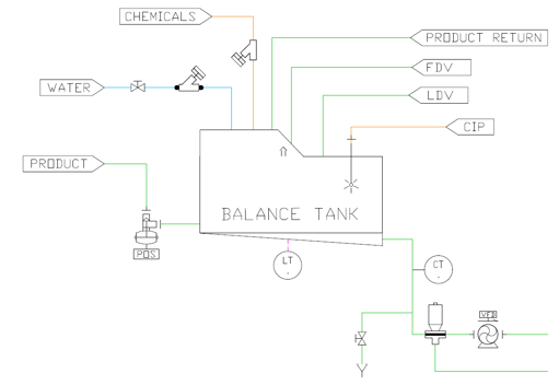
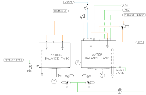
Balance Tank design plays a large role in the efficiency of the product and water changeover of a pasteurizer. Depending on product and application as well as ordinances that must be complied with the Food and Beverage industry, one may or may not have the ability to make efficient balance tank designs. PMO (Pasteurized Milk Ordinance) has specific rules regarding Balance Tanks. In the case of HTST for Grade A milk, the top of the Balance Tank must be lower than the bottom of the PHE (Plate Heat Exchanger), therefore most dairy HTST’s have a design like the one shown in Figure #1 below. However, for HHST (ESL Higher Heat Short Time) or UHT (Ultra High-Temperature Short Time), there is more flexibility on Balance Tank design. JCS typically uses an arrangement as shown in Figure #2 below, with a sump in the bottom of the product Balance Tank which has a small volume with a maximized head, to produce a sharp product to water transition with minimum interface. Coupling this with other design considerations such as Feed Forward Temperature control, in our direct injection system (UltraSys™), and other processing considerations for Deaerators, and Flash Chambers, we always strive to minimize product loss. Below you will find a short description of how the changeovers are controlled.

Figure #1 Typical Single Balance Tank
Single Balance Tank Water to Product
- The level of the Balance Tank is lowered to a minimum level. This level is determined by the amount of positive head pressure required to maintain a net positive suction pressure at the removal pump.
- The product starts to enter the Balance Tank.
- When product flow is confirmed by a rise in the Balance Tank level, the system will start its water to product transition.
- This process creates a volume of water/product interface in the balance tank. It will take some time for the balance tank to become “good” product. All of the interface product will be pumped to drain.
Single Balance Tank Product to Water
- The level of the Balance Tank is lowered to a minimum level. This level is determined by the amount of positive head pressure required to maintain a net positive suction pressure at the removal pump.
- Water starts to enter the Balance Tank.
- The system will start its water to product transition.
- This process creates a volume of water/product interface in the Balance Tank. It will take some time for the balance tank to become clear of the product. All of the interface product will be pumped to drain.

Figure #2 JCS Dual Balance Tank (Dumped Product Tank)
Dual Balance Tank Water to Product
- The system circulates water through the water Balance Tank while the product enters product Balance Tank.
- When the level in the product Balance Tank reaches the set-point, the valves from the product Balance Tank open and the valves from the water Balance Tank are closed. This minimizes the amount of interface, no product and water are mixed in the tanks.
Dual Balance Tank Product to Water
- The level of the product Balance Tank is lowered to a minimum level. This level is determined by the amount of positive head pressure required to maintain a net positive suction pressure at the removal pump. The product Balance Tank is designed with a sump bottom allowing for a narrow column of product to maintain the proper head pressure. In most cases, this volume is only a couple gallons of product. When the level in the product Balance Tank reaches its minimum set-point the valves from the product Balance Tank close and the valves from the water Balance Tank are opened. This minimizes the amount of interface, and there is no mixing in the tanks.


